Virtual Memory
Concepts
Understanding what virtual memory is can be a little tricky. Virtual Memory is a special Memory Addressing Scheme implimented by both the hardware and software. It allows non contigous physical memory to act as if it was contigius memory.
Notice that I said "Memory Addressing Scheme". What this means is that virtual memory allows us to control what a Memory Address refers to.
Virtual Address Space (VAS)
A Virtual Address Space is a Program's Address Space. One needs to take note that this does not have to do with Physical Memory. The idea is so that each program has their own independent address space. This insures one program cannot access another program, because they are using a different address space.
Because VAS is Virtual and not directly used with the physical memory, it allows the use of other sources, such as disk drives, as if it was memory. That is, It allows us to use more "memory" then what is physically installed in the system.
This fixes the "Not enough memory" problem.
Also, as each program uses its own VAS, we can have each program always begin at base 0x0000:0000. This solves the relocation problems discussed ealier, as well as memory fragmentation--as we no longer need to worry about allocating continous physical blocks of memory for each program.
Virtual Addresses are mapped by the Kernel trough the MMU. More on this a little later.
Memory Management Unit (MMU)
The Memory Management Unit (MMU) (Also known as Paged Memory Management Unit (PMMU)) sets between (Or as part of) the microprocessor and the memory controller. While thememory controller's primary function is the translation of memory addresses into a physical memory location, the MMU's purpose is the translation of virtual memory addresses into a memory address for use by the memory controller.
This means--when paging is enabled, all of our memory refrences go through the MMU first!
Translation Lookaside Buffer (TLB)
This is a cache stored within the processor used to improve the speed of virtual address translation. It is useually a type of Content-addressable memory (CAM) where the search key is the virtual address to translate, and the result is the physical frame address. If the address is not in the TLB (A TLB miss), the MMU searches through the page table to find it. If it is found in the TLB, it is aTLB Hit. If the page is not found or invalid inside of the page table during a TLB miss, the processor will raise a Page Fault exception for us.
Think of a TLB as a table of pages stored in a cache instead of in RAM--as that is basically what it is.
This is important! The pages are stored in page tables. We set up these page tables to describe how physical addresses translate to virtual addresses. In other words: The TLB translates virtual addresses into physical addresses using the page tables *we* set up for it to use! Yes, thats right--we set up what virtual addresses map to what. We will look at how to do this a little later, cool? Dont worry--its not that bad ;)
Paged Virtual Memory
Virtual Memory also provides a way to indirectly use more memory then we actually have within the system. One common way of approching this is by using Page files, stored on a hard drive or aswap partition.
Virtual Memory needs to be mapped through a hardware device controller in order to work, as it is handled at the hardware level. This is normally done through the MMU, which we will look at later.
For an example of seeing virtual memory in use, lets look at it in action:
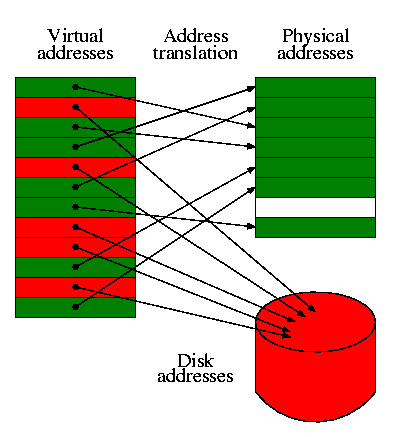
Notice what is going on here. Each memory block within the Virtual Addresses are linear. Each Memory Block is mapped to either it's location within the real physical RAM, or another device, such as a hard disk. The blocks are swapped between these devices as an as needed bases. This might seem slow, but it is very fast thanks to the MMU.
Remember: Each program will have its own Virtual Address Space--shown above. Because each address space is linear, and begins from 0x0000:00000, this immiedately fixes alot of the problems relating to memory fragmentation and program relocation issues.
Also, because Virtual Memory uses different devices in using memory blocks, it can easily manage more then the amount of memory within the system. i.e., If there is no more system memory, we can allocate blocks on the hard drive instead. If we run out of memory, we can either increase this page file on an as needed bases, or display a warning/error message,
Each memory "Block" is known as a Page, which is useually 4096 bytes in size. We will cover Pages a little later.
Okay, so a Page is a memory block. This memory block can either be mapped to a location in memory, or to another device location, such as a hard disk. This is an unmapped page. If software accessed an unmapped page (The page is not currently in memory), it needs to be loaded somehow. This is done by our Page fault handler.
We will cover everything later, so do not worry if this sounds hard :)
Because we are talking about paging in general, I think now would be a good idea to look at some extensions that may be used with paging. Lets have a look!
PAE and PSE
Physical Address Extension (PAE)
PAE is a feature in x86 microprocessors that allows 32 bit systems to access up to 64 GB of physical memory. PAE supported motherboards use a 36 line address bus to achieve this. Paging support with PAE enabled (Bit 5 in the cr4 register) is a little different then what we looked at so far. I might decide to cover this a little later, however to keep this tutorial from getting even more complex, we will not look at it now. However, I do encourage readers to look into it if you are interested. ;)
Page Size Extension (PSE)
PSE is a feature in x86 microprocessors that allows pages more then 4KB in size. This allows the x86 architecture to support 4MB page sizes (Also called "huge pages" or "large pages") along side 4KB pages.
The World of Paging
Let the madness begin :)
Introduction
Woo-hoo! Welcome to the wonderful and twisted-minded world of paging! With all of the fundemental concepts that we have went over already, you should have a nice and good grasp at what paging and virtual memory is all about. This is a great start, don't you think?
Okay, cool...but, how do we actually impliment it? How does paging work on the x86 architecture? Lets take a look!
Pages
A Page (Also known as a memory page or virtual page) is a fixed-length block of memory. This block of memory can reside in physical memory. Think of it like this: A page describes a memory block, and where it is located at. This allows us to "map" or "find" the location of where that memory block is at. We will look at mapping pages and how to impliment paging a little later :)
The i86 architecture uses a specific format for just this. It allows us to keep track of a single page, and where it is currently located at. Lets take a look..
Page Table Entries (PTE)
A page table entry is what represents a page. We will not cover the page table until a little later so dont worry too much about it. However we will need to look at what an entry in the table looks like now. The x86 architecture defines a specific bit format for working with pages, so lets take a look at it.
- Bit 0 (P): Present flag
- 0: Page is not in memory
- 1: Page is present (in memory)
- Bit 1 (R/W): Read/Write flag
- 0: Page is read only
- 1: Page is writable
- Bit 2 (U/S):User mode/Supervisor mode flag
- 0: Page is kernel (supervisor) mode
- 1: Page is user mode. Cannot read or write supervisor pages
- Bits 3-4 (RSVD): Reserved by Intel
- Bit 5 (A): Access flag. Set by processor
- 0: Page has not been accessed
- 1: Page has been accessed
- Bit 6 (D): Dirty flag. Set by processor
- 0: Page has not been written to
- 1: Page has been written to
- Bits 7-8 (RSVD): Reserved
- Bits 9-11 (AVAIL): Available for use
- Bits 12-31 (FRAME): Frame address
Cooldos! Thats all? Well.. I never said it was hard ;)
Quite possibly the most important thing here is the frame address. The frame address represents the 4KB physical memory location that the page manages. This is vital to know when understanding paging, however it is hard to describe why it is so right now. For now, just remember that each and every page manages a block of memory. If the page is present, it manages a 4KB physical address space in physical memory.
The Dirty Flag and Access Flag are set by the processor, not software. You might wonder on how the processor knows what bits to set; ie, where they are located in memory. We will look at that a little later. Just rememeber that, this will allow the software or executive to test if a page has been accessed or not.
The present flag is an important one. This one single bit is used to determin if a page is currently in physical memory or not. If it is currently in physical memory, the frame address is the 32 bit linear address for where it is located at. If it is not in physical memory, the page must reside on another location--such as a hard disk.
If the present flag is not set, the processor will ignore the rest of the bits in the structure. This allows us to use the rest of the bits for whatever purpose...perhaps where the page is located at on disk? This will allow--when our page fault handler gets called--for us to locate the page on disk and swap the page into memory when needed.
Lets give out a simple example. Lets say that we want this page to manage the 4KB address space beginning at physical location 1MB (0x100000). What this means--to put in other words--is that this page is "mapped" to address 1MB.
To create this page, simply set 0x100000 in bits 12-31 (the frame address) of the page, and set the present bit. Voila--the page is mapped to 1MB. :) For example:
%define  PRIV  3

mov  ebx, 0x100000 | PRIV ; this page is mapped to 1MB
Notice that 0x100000 is 4KB aligned? It ORs it with 3 (11 binary which sets the first two bits. Looking at the above table, we can see that it sets the present and read/write flags, making this page present (Meaning its in physical memory. This is true as it is mapped from physical address 0x100000), and is writable.
Thats it! You will see this example expand further in the next few sections so that you can start seeing how everything fits in, so don't worry to much if you still do not understand.
Also notice that there is nothing special about PTEs--they are simply 32 bit data. What is special about them is how they are used. We will look at that a little later...
pte.h and pte.cpp - Abstracting page table entries and pages
The demo hides all of the code to set and get the individual properties of the page table entries inside of these two files. All these do is set and get the bits and frame address from the 32 bit pattern that we have looked at in the list above. This interface does have a little overhead but greatly improves readability and makes it easier to work with them.
The first thing we do is to abstract the bit pattern used by page table entries. This is too easy:
enum PAGE_PTE_FLAGS {

 I86_PTE_PRESENT   = 1,  //0000000000000000000000000000001
 I86_PTE_WRITABLE  = 2,  //0000000000000000000000000000010
 I86_PTE_USER   = 4,  //0000000000000000000000000000100
 I86_PTE_WRITETHOUGH  = 8,  //0000000000000000000000000001000
 I86_PTE_NOT_CACHEABLE  = 0x10,  //0000000000000000000000000010000
 I86_PTE_ACCESSED  = 0x20,  //0000000000000000000000000100000
 I86_PTE_DIRTY   = 0x40,  //0000000000000000000000001000000
 I86_PTE_PAT   = 0x80,  //0000000000000000000000010000000
 I86_PTE_CPU_GLOBAL  = 0x100,  //0000000000000000000000100000000
 I86_PTE_LV4_GLOBAL  = 0x200,  //0000000000000000000001000000000
    I86_PTE_FRAME   = 0x7FFFF000  //1111111111111111111000000000000
};
Notice how this matches up with the bit format that we looked at in the above list. What we want is a way to abstract the setting and getting of these properties (ie, bits) behind the interface.
To do this, we first abstract the data type used to store a page table entry. In our case its a simple uint32_t:
//! page table entry
typedef uint32_t pt_entry;
Simple enough. Next up is the interface routines that are used to set and get these bits. I dont want to look at the implimentation of it as all it does is (litterally) set or get individual bits within a pt_entry. So instead I want to focus on the interface:
extern void   pt_entry_add_attrib (pt_entry* e, uint32_t attrib);
extern void   pt_entry_del_attrib (pt_entry* e, uint32_t attrib);
extern void   pt_entry_set_frame (pt_entry*, physical_addr);
extern bool   pt_entry_is_present (pt_entry e);
extern bool   pt_entry_is_writable (pt_entry e);
extern physical_addr pt_entry_pfn (pt_entry e);
pt_entry_add_attrib() sets a single bit within the pt_entry. We pass it a mask (like our I86_PTE_PRESENT bit mask) to set it. pt_entry_del_attrib() does the same but clears the bit.
pt_entry_set_frame() masks out the frame address (I86_PTE_FRAME mask) to set our frame address to it. pt_entry_pfn() returns this address.
There is nothing special about these routines--we can easily set and get these attributes manually if we wanted to via bit masks or (if you wanted) bit fields. I personally feel this setup makes it much easier to work with though ;)
Okay, this is great as this setup allows us to keep track of a single page. However, it is useless by itself as a typical system will need to have alot of pages. This is where a page table comes in.
Page Tables
The page table...hm...where oh where did we hear that term before? *looks one line up*. Oh, right ;)
A Page Table is..well..a table of pages. (Surprised?) A page table allows us to keep track of how the pages are mapped between physical and virtual addresses. Each page entry in this table follows the format shown in the previous section. In other words, a page table is an array of page table entries (PTEs).
While it is a very simple structure, it has a very important purpose. The page table containes a list of all the pages it containes, and how they are mapped. By "mapping", We refer to how the virtual address "maps" to the physical frame address. The page table also manages the pages, weather they are present, how they are stored, or even what process they belong to (This can be set by using the AVAIL bits of a page. This may not be needed, it depends on the implimentation of the system.)
Lets stop for a moment. Remember that a page manages 4KB of physical address space? By itself, a page is nothing more then a 32 bit data structure that describes the properties of a specific 4KB region of physical memory (Remember this from before?) Because each page "manages" 4KB of physical memory, putting 1024 pages together we have 1024*4KB=4MB of managed virtual memory. Lets take a look at how its set up:
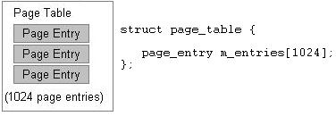
Thats an example of a page table. Notice how it is nothing more then an array 1024 page entries. Knowing that each page manages 4KB of physical memory, we can actually turn this little table into its own virtual address space. How can we do this? Simple: By deciding the format of a virtual address.
Heres an example: Lets say we have designed a new virtual address format like this:
AAAAAAAAAA        BBBBBBBBBBBB
page table index  offset into page
This is our format for a virtual address. So, when paging is enabled, all memory addresses will now follow the above format. For example, lets say we have the following instruction:
mov ecx, [0xc0000]
Here, 0xc0000 will be treated like a virtual address. Lets break it apart:
11000000        000000000000 ; 0xc0000 in binary form
AAAAAAAAAA        BBBBBBBBBBBB
page table index  offset into page
What we are now doing is an example of address translating. We are actually translating this virtual address to see what physical location it refers to. The page table index, 11000000b = 192. This is the page entry inside of our page table. We can now get the base physical address of the 4KB that this page manages. If this page is present (Pages present flag is set), all we need to do is access the pages frame address to access the memory. If this page is NOT present, then generate a page fault--The page data might be somewhere on disk. The page fault handler will allow us to copy the 4KB data for the page into memory somewhere and set the page to present and update its frame address to point to this new 4KB block of physical memory.
Okay okay, I know. This little example of creating a fake "virtual address" might seem silly, but guess what? This is how its actually done! The actual format of a virtual address is a little bit more complex in that there are three sections instead of 2. However, if we omit the first section of the real virtual address format then it would be exactally the same as our above example.
I hope by now you are starting to see how everything fits together, and the importance of page tables.
Page Size
A system with smaller page sizes will require more pages then a system with larger page sizes. Because the table keeps track of all pages, a system with smaller page sizes will also require a larger page table because there are more pages to keep track of. Simple enough, huh?
The i86 architecture supports 4MB (2MB pages if using Page Address Extension (PAE)) and 4KB sized pages.
The important things to note are: Notice how page size may effect the size of page tables.
The Page Directory Table (PDT)
Okay... We are almost done! A page table is a very powerful structure as you have seen. Remember our previous virtual address example? I gave an example of a virtual addressing system where each virtual address was composed of two parts: A page table entry and a offset into that page.
On the x86 architecture, the virtual address format actually uses three sections instead of two: The entry number in a page directory table, the page table index, and the offset into that page.
A Page Directory Table is nothing more then an array of Page Directory Entries. I know I know... How useless and non-informative was that last sentence? ;)
So, anyways, lets first look at a page directory entry. Then we will start looking at the directory table, and where it all fits in...
Page Directory Entries (PDEs)
Page directory entries help provide a way to manage a single page table. Not only do they contain the address of a page table, but they provide properties that we can use to manage them. You will see how all of this fits in within the next section, so dont worry if you dont understand it yet.
Page directory tables are very simularly structured in the way page tables are structured. They are an array of 1024 entries, where the entries follow a specific bit format. The nice thing about the format of page directory entries (PDEs) is that they follow almost the exact same format that page table entries (PTEs) do (in fact they can be interchangeable). There is only a few little bit of details (pun intended ;) ).
Here is the format of a page directory entry:
- Bit 0 (P): Present flag
- 0: Page is not in memory
- 1: Page is present (in memory)
- Bit 1 (R/W): Read/Write flag
- 0: Page is read only
- 1: Page is writable
- Bit 2 (U/S):User mode/Supervisor mode flag
- 0: Page is kernel (supervisor) mode
- 1: Page is user mode. Cannot read or write supervisor pages
- Bit 3 (PWT):Write-through flag
- 0: Write back caching is enabled
- 1: Write through caching is enabled
- Bit 4 (PCD):Cache disabled
- 0: Page table will not be cached
- 1: Page table will be cached
- Bit 5 (A): Access flag. Set by processor
- 0: Page has not been accessed
- 1: Page has been accessed
- Bit 6 (D): Reserved by Intel
- Bit 7 (PS): Page Size
- 0: 4 KB pages
- 1: 4 MB pages
- Bit 8 (G): Global Page (Ignored)
- Bits 9-11 (AVAIL): Available for use
- Bits 12-31 (FRAME): Page Table Base address
Alot of the members here should look familiar from the page table entry (PTE) list that we looked at ealier.
The Present, Read/Write, and access flags are the same as it was with PTEs, however they apply to a page table rather then a page.
page size determins if the pages inside of the page table are 4KB or 4MB.
Page Table Base address bits contain the 4K aligned address of a page table.
pde.h and pde.cpp - Abstracting Page Directory Entries
Simular to what we did with PTEs, we have created an interface to abstract PDEs in the same manner.
enum PAGE_PDE_FLAGS {

 I86_PDE_PRESENT   = 1,  //0000000000000000000000000000001
 I86_PDE_WRITABLE  = 2,  //0000000000000000000000000000010
 I86_PDE_USER   = 4,  //0000000000000000000000000000100
 I86_PDE_PWT   = 8,  //0000000000000000000000000001000
 I86_PDE_PCD   = 0x10,  //0000000000000000000000000010000
 I86_PDE_ACCESSED  = 0x20,  //0000000000000000000000000100000
 I86_PDE_DIRTY   = 0x40,  //0000000000000000000000001000000
 I86_PDE_4MB   = 0x80,  //0000000000000000000000010000000
 I86_PDE_CPU_GLOBAL  = 0x100,  //0000000000000000000000100000000
 I86_PDE_LV4_GLOBAL  = 0x200,  //0000000000000000000001000000000
    I86_PDE_FRAME   = 0x7FFFF000  //1111111111111111111000000000000
};

//! a page directery entry
typedef uint32_t pd_entry;
Not to hard. We use the new type pd_entry to represent a page directory entry. Also, with the PTE interface, we provide a small set of routines used to provide a nice way of setting and getting the bits within the page directory entry:
extern void  pd_entry_add_attrib (pd_entry* e, uint32_t attrib);
extern void  pd_entry_del_attrib (pd_entry* e, uint32_t attrib);
extern void  pd_entry_set_frame (pd_entry*, physical_addr);
extern bool  pd_entry_is_present (pd_entry e);
extern bool  pd_entry_is_user (pd_entry);
extern bool  pd_entry_is_4mb (pd_entry);
extern bool  pd_entry_is_writable (pd_entry e);
extern physical_addr pd_entry_pfn (pd_entry e);
extern void  pd_entry_enable_global (pd_entry e);
Understanding the Page Directory Table
The Page Directory Table is sort of like an array of 1024 page tables. Remember that each page table manages 4MB of a virtual address space? Well... Putting 1024 page tables together we can manage a full 4GB of virtual addresses. Sweet, huh?
Okay, its a little more complex then that, but not that much. The Page Directory Table is actually an array of 1024 page directory entries that follow the format above. Look back at the format of an entry and notice the Page Table Base address bits. This is the address of the page table this directory entry manages.
It may be easier to see it visually, so here you go:
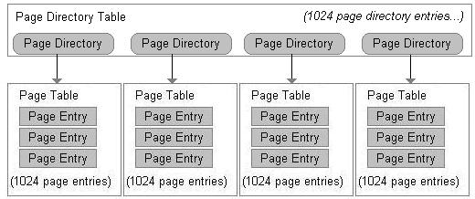
Notice what is happening here. Each page directory entry points to a page table. Remember that each page manages 4KB of physical (and hence virtual) memory? Also, remember that a page table is nothing more then an array of 1024 pages? 1024*4KB = 4MB. This means that each page table manages its own 4MB of address space.
Each page directory entry provides us a way to manage each page table much easier. Because the complete page directory table is an array of 1024 directory entries, and that each entry manages its own table, we effectivly have 1024 page tables. From our previous calculation we know each page table manages 4MB of address space. So 1024 page tables*4MB size= 4GB of virtual address space.
I guess thats it for ... believe it or not... everything. See, its not that hard, is it? In the next section, we will be revisiting the real format of an x86 virtual address, and you will get to see how everything works together!
Use in Multitasking
We run into a small problem here. Remember that a page directory table represents a 4GB address space? How can we allow multiple programs a 4GB address space if we can only have one page directory at a time?
We cant. Not nativly, anyways. Alot of mutitasking operating systems map the high 2 GB address space for its own use as "kernel space" and the low 2 GB as "user space". The user space cannot touch kernel space. With the kernel address space being mapped to every processes 4GB virtual address space, we can simply switch the current page directory without error using the kernel no matter what process is currently running. This is possible do to the kernel always being located at the same place in the processes address space. This also makes scheduling possible. More on that later though...
Virtual Memory Management
We have covered everything we need to develop a good virtual memory manager. A virtual memory manager must provide methods to allocate and manage pages, page tables, and page directory tables. We have looked at each of these in separate, but have not looked at how they work together.
Higher Half Kernels
Abstract
A Higher Half Kernel is a kernel that has a virtual base address of 2GB or above. A lot of operating systems have a higher half kernel. Some examples include the Windows and Linux Kernels. The Windows Kernel gets mapped to either 2GB or 3GB virtual address (depending on if /3gb kernel switch is used), the Linux Kernel gets mapped to 3GB virtual address. The series uses a higher half kernel mapped to 3GB. Higher half kernels must be mapped properly into the virtual address space. There are several methods to achieve this, some of which is listed here.
You might be interested on why we would want a higher half kernel. We can very well run our kernel at some lower virtual address. One reason has to do with v86 tasks. If you want to support v86 tasks, v86 tasks can only run in user mode and within the real mode address limits (0xffff:0xffff), or about 1MB+64k linear address. It is also typical to run user mode programs in the first 2GB (or 3GB on some OSs) as software typically never has a need to access high memory locations.
Method 1
The first design is that we can have the boot loader set up a temporary page directory. With this, the base address of the kernel can be 3GB. The boot loader maps a physical address (typically 1MB) to this base address and calls the kernel's entry point.
This method works, but creates a problem of how the kernel is going to work with managing virtual memory. The kernel can either try to work with the page directory and tables set up by the boot loader, or create a new page directory to manage. If we create a new page directory, the kernel will need to remap itself (1MB physical to the base virtual address of the kernel) or cloning the existing temporary page directory to the new page directory.
At this time, this is the method the series uses. The series boot loader will set up a temporary page directory and maps the kernel to 3GB virtual. The kernel then creates a new page directory during VMM initialization and remaps itself. The kernel must remain position-independent during this set up phase. This is the method we use in our in-house OS.
Method 2
Another possible design is that the boot loader loads the kernel into a physical memory location and keeps paging disabled. The kernel virtual base address would be the virtual address it is supposed to execute at. For example, the boot loader can load and execute the kernel at 1MB physical, although the kernels base address is 3GB.
This method is a little tricky. There has to be a way for the boot loader to know what physical address to load and execute the kernel at, and the kernel has to map itself to its real base virtual address. This is usually done during kernel startup in position-independent code. This can be used in position-dependent code, but the kernel must be able to fix the addresses when accessing data or calling functions. This is the method used in our in-house OS.
Method 3
This method uses Tim Robinson's GDT trick. This can be found in his documentation located
here (*.pdf) This allows your kernel to run at a higher address (its base address) even though it is not loaded there. This trick works do to address wrap around. For example, lets say our kernel is loaded at 1MB physical address, but we want it to appear to be running at 3GB Virtual. The base that we want is X + 3GB = 1MB in this case. Lets look closer.
Remember that the GDT descriptor base address is a DWORD. If the value becomes greater then 0xffffffff, it will wrap around back to 0. 3GB = 0xC0000000. 0xffffffff - 0xc0000000 = 0x3FFFFFFF bytes left until it wraps. We need to add an address that will make this address to point to our physical location (1MB). Knowing we have 0x3FFFFFFF bytes left until our DWORD wraps back to 0, we can add 0x100000 (1MB) + 0x3FFFFFFF = 0x400FFFFF + 1 = 0x40100000.
So, by using the above example, if our kernel is loaded at 1MB physical address but has a real base address of 3GB virtual, we can create a temporary GDT with a base code and data selector of 0x40100000. The processor automatically adds the base selector addresses to the addresses it is accessing. After using LGDT to install this new GDT. After this we are now running at 3GB. This works because the processor will add the cs and ds selector base (40100000) to whatever address that is being referenced. For example, 3GB would be translated by the processor to 1MB in our example as 3GB+base selector ((40100000) = 1MB physical.
This trick is fairly easy to impliment and works well but wont work for 64 bit (Long Mode). After the kernel performs this trick it can set up its page directory and map itself with ease after which can enable paging.
Virtual Addressing and Mapping Addresses
When we enable paging, all memory refrences will be treated as a virtual address. This is very important to know. This means we must set up the structures properly first before enabling paging. If we do not, we can run into an immiedate triple fault--with or without valid exception handlers.
Remember the format of a virtual address? This is the format of a x86 virtual address:
AAAAAAAAAA         BBBBBBBBBB        CCCCCCCCCCCC
directory index    page table index  offset into page
This is very important! This tells the processor (And *us*) alot of information.
The directory index portion tells us what index into the current page directory to look in. Look back up to the Directory Entry Structure format in the previous section. Notice that each directory table entry containes a pointer to a page table. You can also see this within the image again in that section.
Because each index within the directory table points to a page table, this tells us what page table we are accessing.
The page table index portion tells us what page entry within this page table we are accessing.
...And remember that each page entry manages a full 4KB of physical address space? The offset into page portion tells us what byte within this pages physical address space we are refrencing.
Notice what happened here. We have just translated a virtual address into a physical address using our page tables. Yes, its that easy. No trickery involved.
Lets look at another example. Lets assumed that virtual address 0xC0000000 was mapped to physical address 0x100000. How do we do this? We need to find the page in our structures that 0xC0000000 refer to -- just like we did above. In this case 0xC0000000 is the virtual address, so lets look at its format:
1100000000         0000000000        000000000000  ; 0xC0000000 in binary form

AAAAAAAAAA         BBBBBBBBBB        CCCCCCCCCCCC
directory index    page table index  offset into page
Remember that the directory index tells us what page table we are accessing within the page directory table? So... 1100000000b (The directory index) = 768th page table.
Remember that the page table index is the page we are accessing within this page table? That is 0, so its the first page. Also note the offset byte in this page is 0.
Now, all we need to do is set the frame address of the first page in the 768th page table to 0x100000 and voila! You have just mapped 3GB virtual address to 1MB physical! Knowing that each page is 4KB aligned, we can keep doing this in increments of 4KB physical addresses.
Identity Mapping
Identity Mapping is nothing more then mapping a virtual address to the same physical address. For example, virtual address 0x100000 is mapped to physical address 0x100000. Yep--Thats all there is to it. The only real time this is required is when first setting up paging. It helps insure the memory addresses of your current running code of where they are at stays the same when paging is enabled. Not doing this will result in immediate triple fault. You will see an example of this in our Virtual Memory Manager initialization routine.
Memory Managment: Implimentation
Implimentation
I suppose that is everything. What we will look at next is the virtual memory manager (VMM) itself that has been developed for this tutorial. This will bring everything that we have looked at together so that you can see how everything works.
I have tried to make the routines small so that we can focus on one topic at a time as there is a couple of new things that we still need to look at.
Alrighty...First lets take a look at the page table and directory table themselves:
//! virtual address
typedef uint32_t virtual_addr;

//! i86 architecture defines 1024 entries per table--do not change
#define PAGES_PER_TABLE 1024
#define PAGES_PER_DIR 1024

#define PAGE_DIRECTORY_INDEX(x) (((x) >> 22) & 0x3ff)
#define PAGE_TABLE_INDEX(x) (((x) >> 12) & 0x3ff)
#define PAGE_GET_PHYSICAL_ADDRESS(x) (*x & ~0xfff)

//! page table represents 4mb address space
#define PTABLE_ADDR_SPACE_SIZE 0x400000

//! directory table represents 4gb address space
#define DTABLE_ADDR_SPACE_SIZE 0x100000000

//! page sizes are 4k
#define PAGE_SIZE 4096

//! page table
struct ptable {

 pt_entry m_entries[PAGES_PER_TABLE];
};

//! page directory
struct pdirectory {

 pd_entry m_entries[PAGES_PER_DIR];
};
Simular to our physical_addr type, I created a new address type for virtual memory--virtual_addr. Notice that a page table is nothing more then an array of 1024 page table entries? Same thing with the page directory table, but its an array of page directory entries instead. Nothing special yet ;)
PAGE_DIRECTORY_INDEX, PAGE_TABLE_INDEX, PAGE_GET_PHYSICAL_ADDRESS are macros that just returns the respective partion of a virtual address. Remember that a virtual address has a specific format, these macros allow us to obtain the information from the virtual address.
PTABLE_ADDR_SPACE_SIZE represents the size (in bytes) that a page table represents. A page table is 1024 pages, where a page is 4K in size, so it is 1024 * 4k = 4MB.DTABLE_ADDR_SPACE_SIZE represents the number of bytes a page directory manages, which is the size of the virtual address space. Knowing a page table represents 4MB of the address space, and that a page directory contains 1024 page tables, 4MB * 1024 = 4GB.
The virtual memory manager presented here does not handle large pages. Instead, it only manages 4K pages.
The Virtual Memory Manager (VMM) we use relies on these structures heavily. Lets take a look at some of the routines in the VMM to learn how they work.
vmmngr_alloc_page () - allocates a page in physical memory
To allocate a page, all we need to do is allocate a 4K block of physical memory for the page to refer to, then simply create a page table entry from it:
bool vmmngr_alloc_page (pt_entry* e) {

 //! allocate a free physical frame
 void* p = pmmngr_alloc_block ();
 if (!p)
  return false;

 //! map it to the page
 pt_entry_set_frame (e, (physical_addr)p);
 pt_entry_add_attrib (e, I86_PTE_PRESENT);

 return true;
}
Notice how our PTE routines make this much easier to do? The above sets the PRESENT bit in the page table entry and sets its FRAME address to point to our allocated block of memory. Thus the page is present and points to a valid block of physical memory and is ready for use. Cool, huh?
Also, notice how we "map" the physical address to the page. All this means is that we set the page to point to a physical address. Thus the page is "mapped" to that address.
vmmngr_free_page () - frees a page in physical memory
To free a page is even easier. Simply free the block of memory using our physical memory manager, and clear the page table entries PRESENT bit (marking it NOT PRESENT) :
void vmmngr_free_page (pt_entry* e) {

 void* p = (void*)pt_entry_pfn (*e);
 if (p)
  pmmngr_free_block (p);

 pt_entry_del_attrib (e, I86_PTE_PRESENT);
}
Thats it! Now that we have a way to allocate and free a single page, lets see if we can put them together in full page tables...
vmmngr_ptable_lookup_entry () - get page table entry from page table by address
Now that we have a way of abtaining the page table entry number from a virtual address, we need a way to get it from the page table. This routine does just that! It uses the above function to convert the virtual address into an index into the page table array, and returns the page table entry from it.
inline pt_entry* vmmngr_ptable_lookup_entry (ptable* p,virtual_addr addr) {

 if (p)
  return &p->m_entries[ PAGE_TABLE_INDEX (addr) ];
 return 0;
}
Because this routine returns a pointer, we can modify the entry as much as we need to as well. Cool?
Thats it for the page table routines. See how easy paging is? ;)
Next up...The page directory routines!
vmmngr_pdirectory_lookup_entry () - get directory entry from directory table by address
Now that we have a way to covert a virtual address into a page directory table index, we need to provide a way to get the page directory entry from it. This is exactally the same with the page table routine counterpart:
inline pd_entry* vmmngr_pdirectory_lookup_entry (pdirectory* p, virtual_addr addr) {

 if (p)
  return &p->m_entries[ PAGE_TABLE_INDEX (addr) ];
 return 0;
}
vmmngr_switch_pdirectory () - switch to a new page directory
Notice how small all of these routines are. They provide a minimal but very effective interface for easily working with page tables and directories. When we set up a page directory, we need to provide a way to install it for our use.
In the previous tutorial, we added two routines: pmmngr_load_PDBR() and pmmngr_get_PDBR() to set and get the Page Directory Base Register (PDBR). This is the register that stores the current page directory table. On the x86 architecture, the PDBR is the cr3 processor register. Thus, these routines simply set and gets the cr3 register.
vmmngr_switch_pdirectory () uses these routines to load the PDBR and set the current directory:
//! current directory table (global)
pdirectory*  _cur_directory=0;

inline bool vmmngr_switch_pdirectory (pdirectory* dir) {

 if (!dir)
  return false;

 _cur_directory = dir;
 pmmngr_load_PDBR (_cur_pdbr);
 return true;
}

pdirectory* vmmngr_get_directory () {

 return _cur_directory;
}
vmmngr_flush_tlb_entry () - flushes a TLB entry
Remember how the TLB caches the current page table? Sometimes it may be necessary to flush (invalidate) the TLB or individual entries so that it can get updated to the current value. This may be done automatically by the processor (Like during a mov instruction involving a control register).
The processor provides a method for us to manually flush individual TLB entries ourself. This is done using the INVLPG instruction.
We simply pass it the virtual address and the resulting page entry will be invalidated:
void vmmngr_flush_tlb_entry (virtual_addr addr) {

#ifdef _MSC_VER
 _asm {
  cli
  invlpg addr
  sti
 }
#endif
}
Keep in mind that INVLPG is a privlidged instruction. Thus you must be running in supervisor mode to use it.
vmmngr_map_page () - maps pages
This is one of the most important routines. This routine allows us to map any physical address to a virtual address. Its a little complicated so lets break it down:
void vmmngr_map_page (void* phys, void* virt) {

   //! get page directory
   pdirectory* pageDirectory = vmmngr_get_directory ();

   //! get page table
   pd_entry* e = &pageDirectory->m_entries [PAGE_DIRECTORY_INDEX ((uint32_t) virt) ];
   if ( (*e & I86_PTE_PRESENT) != I86_PTE_PRESENT) {
We are given a physical and virtual address as paramaters. The first thing that must be done is to verify that the page directory entry that this virtual address is located in is valid (That is, has been allocated before and its PRESENT bit is set.)
The page directory index is part of the virtual address itself, so we use PAGE_DIRECTORY_INDEX() to obtain the page directory index. Then we just index into the page directory array to obtain a pointer to the page directory entry. Then the test to see if I86_PTE_PRESENT bit is set or not. If it is not set, then the page directory entry does not exist so we must create it...
//! page table not present, allocate it
      ptable* table = (ptable*) pmmngr_alloc_block ();
      if (!table)
         return;

      //! clear page table
      memset (table, 0, sizeof(ptable));

      //! create a new entry
      pd_entry* entry =
         &pageDirectory->m_entries [PAGE_DIRECTORY_INDEX ( (uint32_t) virt) ];

      //! map in the table (Can also just do *entry |= 3) to enable these bits
      pd_entry_add_attrib (entry, I86_PDE_PRESENT);
      pd_entry_add_attrib (entry, I86_PDE_WRITABLE);
      pd_entry_set_frame (entry, (physical_addr)table);
   }
The first thing the above does is to allocate a new page for the new page table and clears it. After words, it uses PAGE_DIRECTORY_INDEX() again to get the directory index from the virtual address, and indexes into the page directory to get a pointer to the page table entry. Then it sets the page table entry to point to our new allocate page table, and sets its PRESENT and WRITABLE bits so that it can be used.
At this point, the page table is guaranteed to be valid at that virtual address. So the routine now just needs to map the address...
//! get table
   ptable* table = (ptable*) PAGE_GET_PHYSICAL_ADDRESS ( e );

   //! get page
   pt_entry* page = &table->m_entries [ PAGE_TABLE_INDEX ( (uint32_t) virt) ];

   //! map it in (Can also do (*page |= 3 to enable..)
   pt_entry_set_frame ( page, (physical_addr) phys);
   pt_entry_add_attrib ( page, I86_PTE_PRESENT);
}
The above calls PAGE_GET_PHYSICAL_ADDRESS() to get the physical frame that the page directory entry points to in order to get the page table entry. Then, using PAGE_TABLE_INDEX to get the page table index from the virtual address, indexing into the page table it obtains the page table entry. Then it sets the page to point to the physical address and sets the pages PRESENT bit.
vmmngr_initialize () - initialize the VMM
This is an important routine. This uses all of the above routines (Well, most of them ;) ) to set up the default page directory, install it, and enable paging. We can also use this an example of how everything works and fits together. Because this routine creates a new page directory, we also need to map 1MB physical to 3GB virtual in order for the kernel.
This is a fairly big routine so lets break it down and see whats going on:
void vmmngr_initialize () {

 //! allocate default page table
 ptable* table = (ptable*) pmmngr_alloc_block ();
 if (!table)
  return;

 //! allocates 3gb page table
 ptable* table2 = (ptable*) pmmngr_alloc_block ();
 if (!table2)
  return;

 //! clear page table
 vmmngr_ptable_clear (table);
Remember how page tables must be located at 4K aligned addresses? Thanks to out physical memory manager (PMM), our pmmngr_alloc_block() already does just this so we do not need to worry about it. Because a single block allocated is already 4K in size, the page table has enough storage space for its entries as well (1024 page table entries * 4 bytes per entry (size of page table entry) = 4K) so all we need is a single block.
Afterwords we clear out the page table to clean it up for our use.
//! 1st 4mb are idenitity mapped
 for (int i=0, frame=0x0, virt=0x00000000; i<1024; i++, frame+=4096, virt+=4096) {

   //! create a new page
  pt_entry page=0;
  pt_entry_add_attrib (&page, I86_PTE_PRESENT);
   pt_entry_set_frame (&page, frame);

  //! ...and add it to the page table
  table2->m_entries [PAGE_TABLE_INDEX (virt) ] = page;
 }
This parts a little tricky. Remember that as soon as paging is enabled, all address become virtual? This poses a problem. To fix this, we must map the virtual addresses to the same physical addresses so they refer to the same thing. This is idenitity mapping.
The above code idenitity maps the page table to the first 4MB of physical memory (the entire page table). It creates a new page and sets its PRESENT bit followed by the frame address we want the page to refer to. Afterwords it converts the current virtual address we are mapping (stored in "frame") to a page table index to set that page table entry.
We increment "frame" for each page in the page table (stored in "i") by 4K (4096) as that is the block of memory each page refrences. (Remember page table index 0 references address 0 - 4093, index 1 refrences address 4096--etc..?)
Here we run into a problem. Because the boot loader maps and loads the kernel directly to 3gb virtual, we also need to remap the area where the kernel is at:
//! map 1mb to 3gb (where we are at)
 for (int i=0, frame=0x100000, virt=0xc0000000; i<1024; i++, frame+=4096, virt+=4096) {

  //! create a new page
  pt_entry page=0;
  pt_entry_add_attrib (&page, I86_PTE_PRESENT);
  pt_entry_set_frame (&page, frame);

  //! ...and add it to the page table
  table->m_entries [PAGE_TABLE_INDEX (virt) ] = page;
 }
This code is pretty much the same as the above loop and maps 1MB physical to 3GB virtual. This is what maps the kernel into the address space and allows the kernel to continue running at 3GB virtual address.
//! create default directory table
 pdirectory* dir = (pdirectory*) pmmngr_alloc_blocks (3);
 if (!dir)
  return;

 //! clear directory table and set it as current
 memset (dir, 0, sizeof (pdirectory));
The above creates a new page directory and clears it for our use.
pd_entry* entry = &dir->m_entries [PAGE_DIRECTORY_INDEX (0xc0000000) ];
 pd_entry_add_attrib (entry, I86_PDE_PRESENT);
 pd_entry_add_attrib (entry, I86_PDE_WRITABLE);
 pd_entry_set_frame (entry, (physical_addr)table);

 pd_entry* entry2 = &dir->m_entries [PAGE_DIRECTORY_INDEX (0x00000000) ];
 pd_entry_add_attrib (entry2, I86_PDE_PRESENT);
 pd_entry_add_attrib (entry2, I86_PDE_WRITABLE);
 pd_entry_set_frame (entry2, (physical_addr)table2);
Remember that each page table represents a full 4MB virtual address space? Knowing that each page directory entry points to a page table, we can saftley say that each page directory entry represents the same 4MB address space inside of the 4GB virtual address space of the entire directory table. The first entry in the page directory is for the first 4MB, the second is for the next 4MB and so on. Because we are only mapping the first 4MB right now, all we need to do is set the first entry to point to our page table.
In a simular way, we set up a page directory entry for 3GB. This is needed so we can map the kernel in.
Notice that we also set the page directory entries PAGE and PRESENT bit as well. This will tell the processor that the page table is present and writable.
//! store current PDBR
 _cur_pdbr = (physical_addr) &dir->m_entries;

 //! switch to our page directory
 vmmngr_switch_pdirectory (dir);

 //! enable paging
 pmmngr_paging_enable (true);
}
Now that the page directory is set up, we install the page directory and enable paging. If everything worked as expected, your program should not crash. If it does not work, it will probably triple fault.
Page Faults
As you know, as soon as we enable paging all addresses become virtual. All of these virtual addresses rely heavily on the page tables and page directory data structures. This is fine, but there will be alot of times when a virtual address requires the cpu to access a page that is not yet valid. This is when a page fault exception (#PF) is raised by the processor. A will only occur when a page is marked not present. A General Protecton Fault (#GPF) will occur if the page is not properly mapped but marked present and accessable. A #GPF will also occur if the page is not accessable.A page fault is cpu interrupt 14 which also pushes an error code so that we can abtain information. The error code pushed by the processor has the following format:
- Bit 0:
- 0: #PF occured because page was present
- 1: #PF occured NOT because the page was present
- Bit 1:
- 0: Operation that caused the #PF was a read
- 1: Operation that caused the #PF was a write
- Bit 2:
- 0: Processor was running in ring 0 (kernel mode)
- 1: Processor was running in ring 3 (user mode)
- Bit 3:
- 0: #PF did not occure because reserved bits were written over
- 1: #PF occured becaused reserved bits were written over
- Bit 4:
- 0: #PF did not occure during an instruction fetch
- 1: #PF occured during an instruction fetch
All other bits are 0.
When a #PF occures, the processor also stores the address that caused the fault in the
CR2 register.
Normally when a #PF occurs, an operating system will need to fetch the page from the faulting address of the currently running program from disk. This requires several different components of an OS (disk driver, file system driver, volume/mount points management) that we do not yet have. Because of this, we will return back to page fault handling a little later when we have a more evolved OS.


